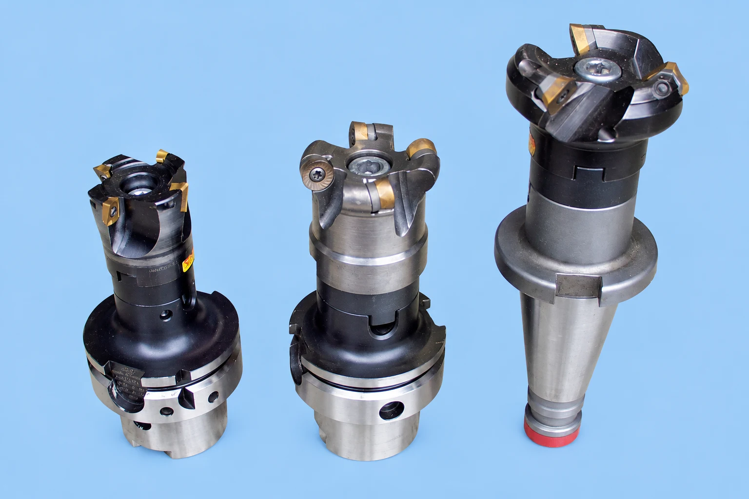

Quick answer: material is the first filter, not the complete answer
Aluminum, steel and stainless steel form chips differently and create different heat, adhesion and edge-load conditions. Use the exact alloy and hardness to narrow the tool geometry, substrate, coating and chipbreaker, then account for operation, engagement, rigidity, coolant and finish.
A colour or broad label such as “for metal” is not enough. The same material may need different tools for slotting, finishing, interrupted turning or deep drilling.
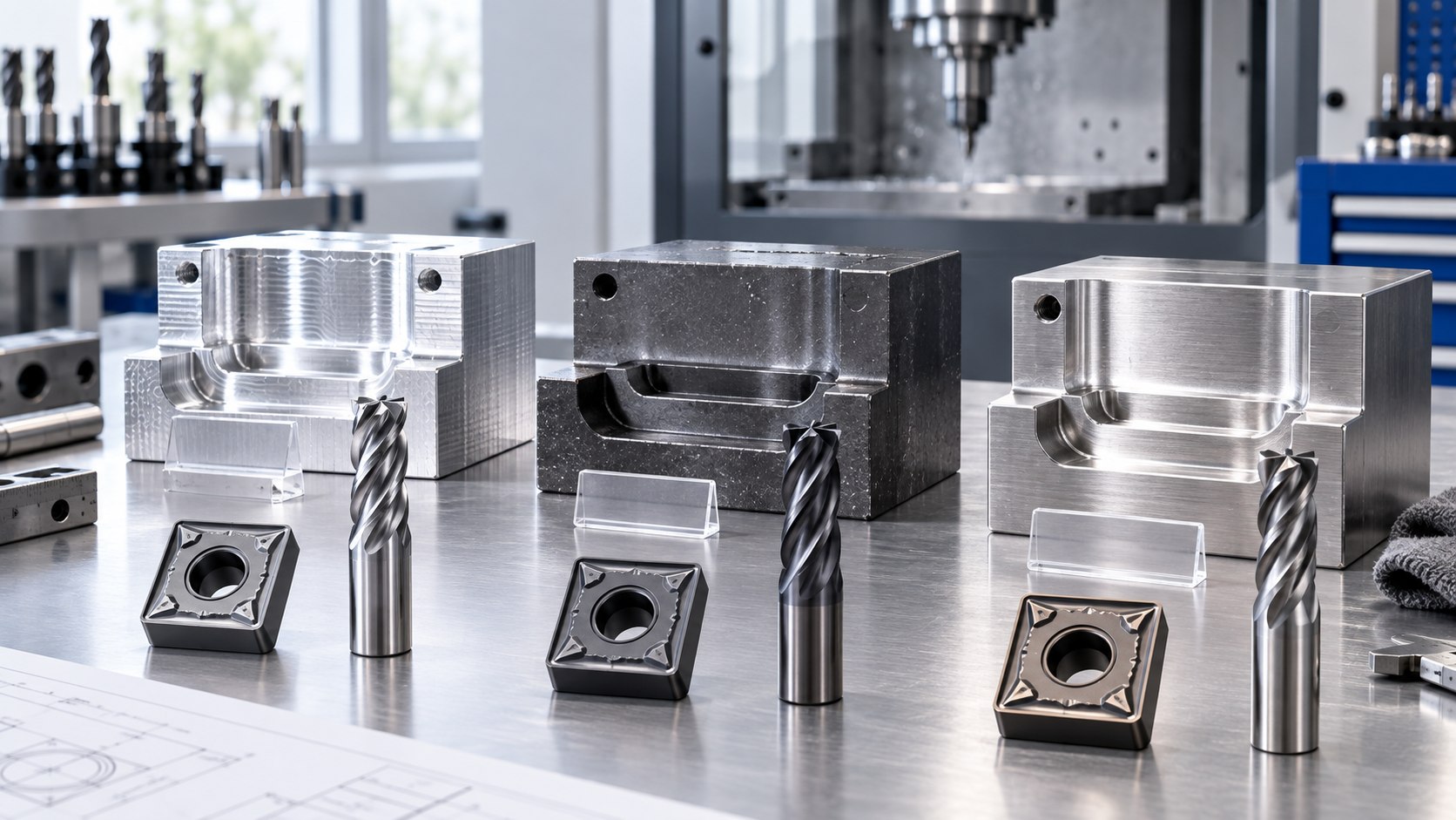
Why the workpiece material comes first
Cutting tools fail at the interface between the edge and the workpiece. Material composition, hardness, microstructure, scale and heat treatment influence chip shape, cutting force, temperature, abrasion, adhesion and chemical wear. A correct selection process therefore starts with a recognised material designation rather than a visual guess.
Supplier catalogues commonly organise application data into ISO material groups such as P for steels, M for stainless steels, K for cast irons, N for non-ferrous materials, S for heat-resistant superalloys and titanium, and H for hardened materials. These groups are useful routing labels, not one cutting speed for every alloy inside the group.
| Workpiece | Typical risks to check | Tool-selection focus |
|---|---|---|
| Aluminum | Adhesion, built-up edge, long chips, chip recutting | Sharp edge, polished flute or rake, chip space and lubrication |
| Carbon or alloy steel | Abrasion, crater wear, scale, interruption | Balance wear resistance and edge toughness |
| Stainless steel | Work hardening, heat concentration, notch wear, stringy chips | Positive cutting action, stable feed, heat control and chip formation |
Selecting tools for aluminum and non-ferrous alloys
Protect chip space
Many aluminum alloys produce a relatively large chip volume. Slotting and deep pockets leave less escape space, so an open flute form, effective air or coolant delivery and a toolpath that avoids chip recutting matter. This is why two- and three-flute end mills remain common, although modern four- and five-flute aluminum tools can work in suitable engagements.
Control adhesion at the edge
A sharp, smooth cutting edge reduces the tendency for material to weld to the tool. Polished flutes or rake faces are common design features. Coating selection must preserve the intended sharpness and surface behaviour; an uncoated tool is an option, not a universal rule.
Identify the alloy
Wrought aluminum, cast aluminum and high-silicon alloys do not create the same wear. Silicon can increase abrasion. Record the alloy designation, temper and whether the surface includes oxide, casting skin or interrupted features.
For a focused decision, see when a 4-flute end mill can machine aluminum and compare 3-flute aluminum end mills with 4-flute flat end mills.
Selecting tools for carbon and alloy steels
Match toughness to the cut
A stable continuous finishing cut can use a more wear-resistant choice than a roughing cut across scale, keyways or interrupted surfaces. When edges chip before a normal wear land develops, increasing nominal hardness alone can make the result worse. Review edge support, grade toughness and setup stability together.
Consider scale and hardness variation
Forgings, flame-cut surfaces and rolled scale can create abrasive or intermittent entry. State whether the cut begins below the skin or must remove it. Provide hardness in HB or HRC where available, especially after heat treatment.
Separate geometry from coating
Chipbreaker geometry controls how the chip forms and where load is supported. The coating influences wear, friction and heat behaviour. A suitable coating cannot compensate for a chipbreaker that is outside its depth-of-cut and feed range.
Selecting tools for stainless steel
Avoid rubbing and work hardening
Some stainless steels harden locally when the edge rubs instead of cutting. Use a stable setup, suitable positive cutting action and a feed that maintains chip formation. Repeated dwell or hesitant manual feed can damage the next pass.
Manage heat and notch wear
Heat can concentrate near the edge, while the depth-of-cut line can develop notch wear. Coolant strategy, edge preparation and toolpath consistency need to be considered with the grade. Do not copy a steel parameter merely because both workpieces look similar.
Specify the stainless family
Austenitic, ferritic, martensitic and duplex stainless steels differ. A generic “stainless” inquiry leaves too much uncertainty for reliable grade or cutting-data selection.
Five variables that can overturn the material-only choice
- Operation: slotting, side milling, facing, boring and drilling load the edge differently.
- Engagement: radial and axial depth control chip thickness, heat and available evacuation space.
- Rigidity: machine, holder, overhang, workholding and workpiece wall thickness form one system.
- Coolant or air: delivery at the cutting zone matters more than a broad “wet” or “dry” label.
- Finish and tolerance: roughing and finishing require different edge support and runout control.
For end mills, flute count changes chip space and core strength. For turning inserts, use the insert-shape comparison before selecting the chipbreaker and grade.
Use the failure mode to refine the next selection
| Observed result | Possible contributors to check | Useful evidence |
|---|---|---|
| Built-up edge | Adhesion, heat, edge finish, lubrication, chip recutting | Edge macro photo and chip sample |
| Chipping | Impact, runout, interruption, weak edge, vibration | Entry location and damaged corner pattern |
| Rapid flank wear | Abrasion, speed, grade, hard skin | Wear progression by time or parts |
| Notch at depth line | Surface hardening, scale, heat, repeated contact line | Depth of cut and workpiece surface condition |
| Burr or poor finish | Dull edge, runout, deflection, unstable chip formation | Surface direction, burr location and tool offset |
Change one controlled variable at a time. If geometry, grade, speed and coolant all change together, the trial cannot show which decision improved or harmed the process.
Information needed for a useful recommendation
- material standard, alloy, condition and hardness;
- operation and part drawing or clear photographs;
- tool diameter or complete insert and holder codes;
- radial and axial engagement, hole depth or turning depth;
- machine spindle, interface, coolant and workholding;
- current cutting data, tool life and failure mode;
- required tolerance, finish and order quantity.
Frequently asked questions
Can one tool grade machine aluminum, steel and stainless steel?
Some general-purpose tools cover several groups, but that does not make one geometry and coating optimal for every operation.
Is an uncoated tool always best for aluminum?
No. Edge sharpness and adhesion control matter, but the actual alloy, operation and available coated tool design still decide the choice.
Why does stainless steel need special attention?
Many stainless steels concentrate heat and can work-harden, so stable cutting action and continuous chip formation are important.
Why are fixed speeds and feeds not listed here?
Reliable values require the exact tool, material, diameter, engagement, coolant and machine limits.
Manufacturer references
Need help confirming the exact tool specification?
Send the model code, clear tool photos, workpiece material and machining task. We will review compatibility and application details before confirming available options, price and lead time.