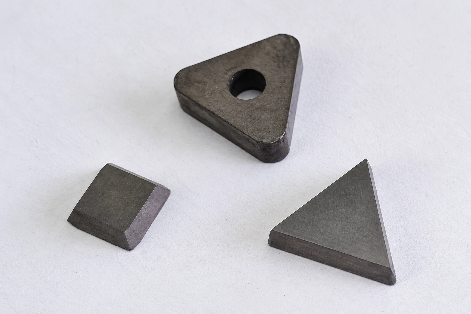

Quick answer: choose the cutting corner first, then verify the complete interface
CNMG, TNMG, WNMG, VNMG and SNMG are different negative turning-insert families. They are not five grades of the same insert. Their outlines change corner strength, profile access, number of usable cutting edges and the holder pocket required.
Start with the operation and workpiece profile. Use the strongest corner that can reach the required surface without interference, then match size, thickness, nose radius, hole, clamping arrangement, chipbreaker and grade. Never select a replacement from the first letter or overall width alone.
What the family code tells you—and what it does not
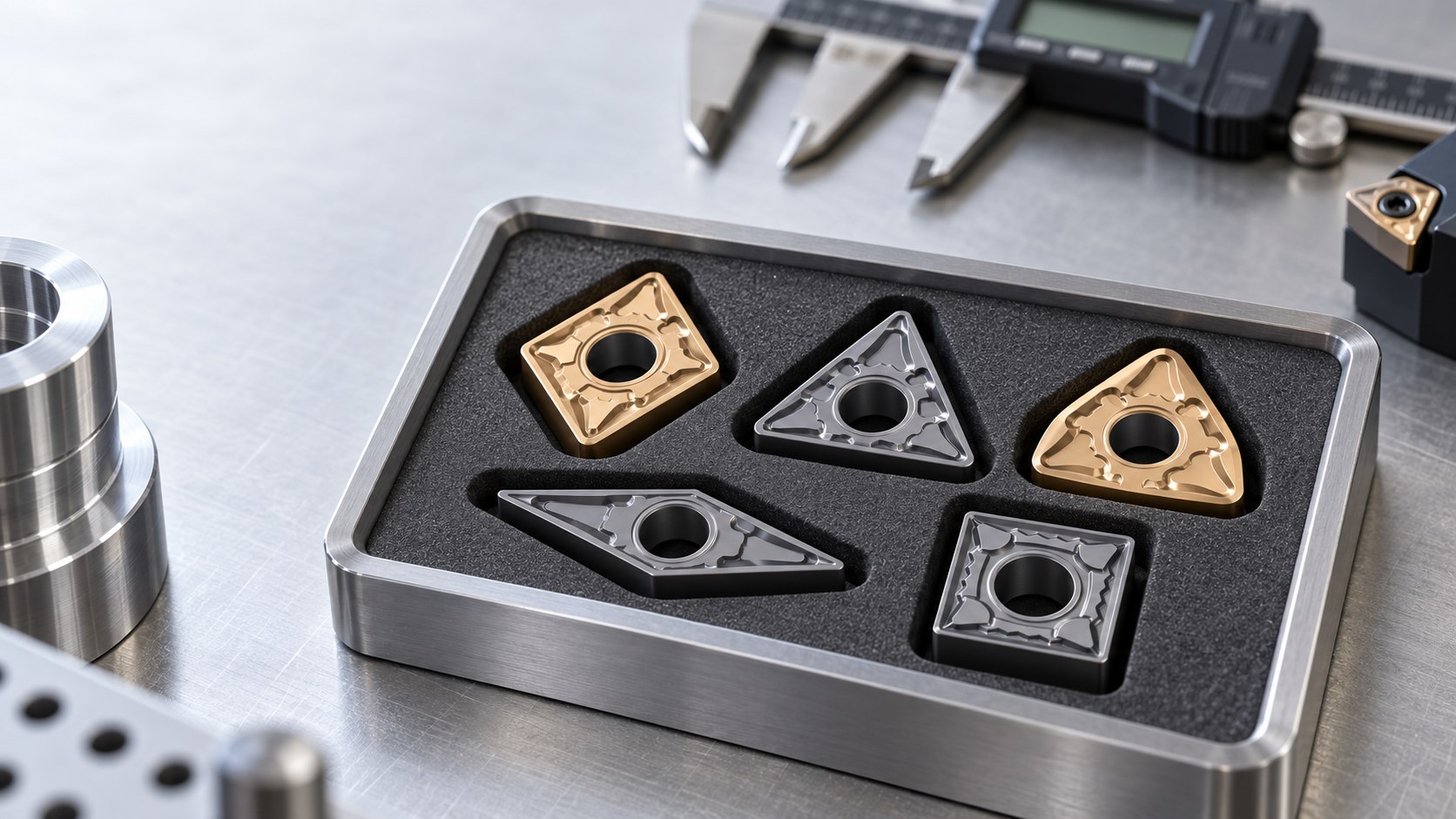
ISO 1832 provides a designation system for common indexable inserts. In the five families compared here, the first letter identifies the outline: C is an 80° rhombus, T is a triangle, W is an 80° trigon, V is a 35° rhombus and S is a square. The second letter N denotes 0° major clearance, so these are negative insert families that rely on the holder to present the cutting edge correctly.
The remaining letters and numbers are not optional details. They describe tolerance, insert type, nominal size, thickness and nose radius. Supplier suffixes then identify chipbreaker, edge preparation, substrate and coating. Therefore “CNMG” narrows the family but does not identify one purchasable specification.
Shape comparison for practical selection
| Family | Nominal corner | Potential edges | Main geometry advantage | Main limitation |
|---|---|---|---|---|
| CNMG | 80° rhombus | 8 | Strong general-purpose corner with useful approach options | Less profile access than acute shapes |
| TNMG | 60° triangle | 6 | Balance of access, economy and corner strength | Less robust than an 80° or 90° corner |
| WNMG | 80° trigon | 6 | Stable 80° corner in a compact trigon outline | Fewer potential edges than CNMG |
| VNMG | 35° rhombus | 4 | Excellent clearance for profiles and undercuts | Acute corner is more sensitive to load and interruption |
| SNMG | 90° square | 8 | Very strong corner for stable, accessible cuts | Most restricted around shoulders and complex profiles |
“Potential edges” is a geometry count, not a guaranteed economic result. Holder hand, approach angle, chipbreaker orientation and damage can make some corners unavailable in a specific operation.
Start with the operation, not the price per edge
Longitudinal turning and facing
Check the feed direction, approach angle and shoulder geometry together. A strong corner can carry load well, but it is useless if the holder and insert collide with the shoulder. For parts that combine outside turning and facing, the required transitions often determine the practical family.
Profiling and copied contours
VNMG and other acute shapes provide access around changing contours, but the smaller included corner needs controlled depth of cut, feed and setup rigidity. Do not choose an acute insert for access and then apply the load expected from a stronger 80° corner.
Roughing and interrupted cuts
Stable roughing generally favours a robust corner, supported edge and suitable tough grade. Interruption, scale, casting skin and keyways increase impact. The family, chipbreaker, edge preparation and substrate must be selected as one system.
Corner strength and profile access pull in opposite directions
A larger included corner leaves more carbide behind the cutting edge. This normally improves mechanical support, while a more acute corner improves access. That trade-off is why no family wins every job.
- Use SNMG only where the 90° square outline clears the part and holder path.
- Use CNMG or WNMG as robust 80° options when the profile permits.
- Use TNMG when a 60° outline provides the needed compromise.
- Use VNMG when access is decisive and cutting load can be controlled.
Nose radius is another independent variable. A larger radius can strengthen the tip and support feed, but it can raise radial cutting force and vibration risk. A smaller radius improves access but requires attention to edge strength and programmed compensation.
Why similar corners do not share a holder
Outline and locating surfaces must match
CNMG and WNMG can both present an 80° cutting corner, but one is rhombic and the other trigon-shaped. Their seats, locating walls and pocket footprints are different. A centre screw entering the hole does not prove correct support.
Size and thickness are part of the interface
Two inserts from the same family can carry different size codes. Match the complete holder designation with the current manufacturer compatibility table. If the holder code is unreadable, photographs and dimensions can narrow the options, but a trial fit should not replace specification control.
Inspect the pocket before blaming the insert
Chips under the seat, a cracked shim, damaged locating wall, stretched screw or worn clamp can allow a correct insert to move. Clean and inspect the complete assembly when finish, size or edge life changes unexpectedly.
For the common forum question about mixing C-shaped positive and negative inserts, see whether a CCMT insert can fit a CNMG holder. It is a separate interface problem from choosing between negative families.
A repeatable selection workflow
- Define the operation: outside turning, facing, boring, profiling, roughing or finishing.
- Map the part profile: mark shoulders, reliefs and surfaces that create interference risk.
- Choose corner strength: select the strongest outline that still reaches the required geometry.
- Confirm the holder: hand, approach, pocket, clamping style and insert size must agree.
- Select nose radius and chipbreaker: relate them to depth, feed, chip control and finish.
- Select grade and coating: use workpiece material, hardness, interruption and coolant condition.
- Run a controlled trial: record wear mode, chips, surface finish, power and dimensional stability.
What to send for model matching
| Evidence | Why it matters |
|---|---|
| Full insert code and box label | Preserves family, size, radius, chipbreaker and grade |
| Complete holder code | Confirms pocket, hand and approach |
| Part drawing or profile photo | Reveals access and interference constraints |
| Material and hardness | Guides grade, coating and edge selection |
| Current problem | Separates chipping, wear, chatter, finish and chip-control issues |
| Quantity and repeat-order record | Supports sampling, quotation and traceability |
Browse the relevant families: CNMG turning inserts, TNMG turning inserts, WNMG turning inserts, VNMG turning inserts and SNMG turning inserts.
Frequently asked questions
Which turning insert shape is best for general turning?
There is no universal best shape. Use the strongest corner that clears the part profile and matches a suitable holder, then select chipbreaker and grade for the operation.
Can CNMG and WNMG use the same holder?
No. Their outlines and pocket interfaces differ even though both can present an 80° cutting corner.
Why does VNMG reach profiles more easily?
Its 35° acute corner provides more clearance, but that corner is less robust and needs controlled loading.
Does the family code define the carbide grade?
No. Grade, coating and chipbreaker remain separate supplier-specific choices.
Standards and technical references
Need help confirming the exact tool specification?
Send the model code, clear tool photos, workpiece material and machining task. We will review compatibility and application details before confirming available options, price and lead time.