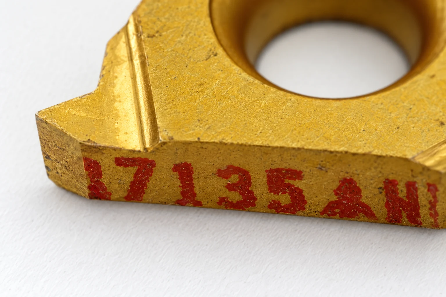

Quick answer: read the designation from left to right, but keep supplier suffixes separate
A turning-insert code is a sequence, not a product nickname. Under ISO 1832, the first positions identify shape, clearance, tolerance and insert type. The following positions identify nominal size, thickness and corner radius. Additional chipbreaker and grade suffixes usually belong to the supplier’s own system.
Always retain the complete original code. A partial code such as CNMG or WNMG cannot confirm physical fit, cutting behaviour or a repeat-order specification.
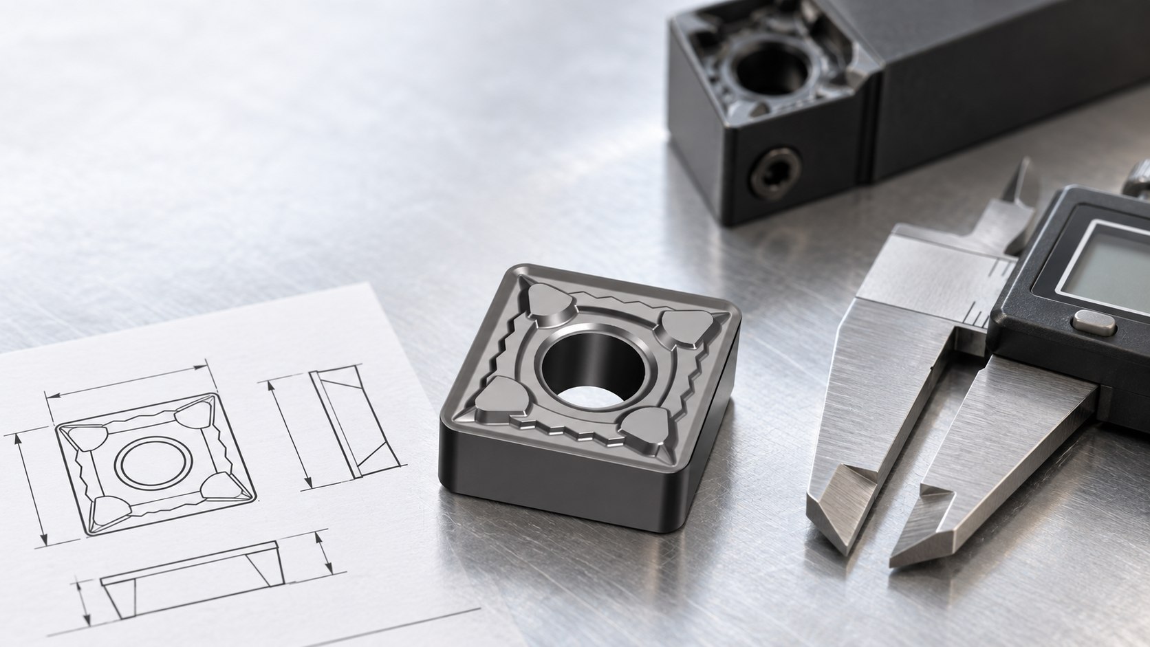
What ISO 1832 covers
ISO 1832:2017 establishes a designation code for common indexable inserts made from hard cutting materials. Its purpose is to simplify ordering and specification. The standard was confirmed in 2022 and remains current at the time of this guide.
The code is extremely useful, but it does not make every commercial suffix universal. Chipbreaker names, coating names and grade numbers can remain manufacturer-specific. That boundary matters when comparing suppliers: standard positions can be decoded across catalogues, while private suffixes need their own evidence.
The first four letters define the geometry family
| Position | Meaning | Practical check |
|---|---|---|
| 1 | Insert shape | Corner angle, outline and access to the workpiece profile |
| 2 | Major clearance angle | Positive or negative geometry and pocket presentation |
| 3 | Tolerance class | Dimensional control for size and locating features |
| 4 | Insert type | Hole, countersink, chipbreaker form and clamping interface |
Position 1: shape
Common examples include C for an 80° rhombus, D for a 55° rhombus, T for a triangle, V for a 35° rhombus, W for an 80° trigon and S for a square. Two shapes can share a cutting-corner angle without sharing the same outline. CNMG and WNMG therefore require different pockets.
Position 2: clearance
N denotes 0° major clearance in common negative turning inserts. C denotes 7° clearance in families such as CCMT. This difference changes support and cutting position. The first letter alone is not enough to judge compatibility.
Positions 3 and 4: tolerance and type
Tolerance controls nominal dimensional limits, while the type position describes important physical details such as the fixing hole and chipbreaker arrangement. A similar top view can hide different side geometry, countersink or locating features.
The number positions define nominal dimensions
The numerical portion commonly represents nominal insert size, thickness and nose radius. Exact decoding depends on the applicable metric or ANSI convention and the insert shape. Do not turn the code into a measurement with a single universal multiplier.
Nominal size
For many shapes this position relates to an inscribed circle; for others, a cutting-edge length convention is used. The current manufacturer drawing is the final dimensional reference. For example, the difference between WNMG 080408 and WNMG 060408 changes the nominal pocket size even when thickness and radius positions appear the same.
Thickness
Thickness affects pocket support, cutting-edge height and clamp geometry. A thinner insert should never be packed up with improvised material, and a thicker insert should not be forced into the pocket.
Nose radius
The final common position identifies nominal corner radius in the applicable system. Radius affects edge strength, cutting force, surface generation and programmed compensation. Confirm the machine’s tool record when changing it.
Why chipbreaker and grade suffixes require supplier data
A code may continue with letters or numbers after the standard dimensional positions. These can identify chipbreaker, edge preparation, substrate, coating or a commercial grade. Their meanings are not reliably transferable between brands.
- Do not identify a grade from coating colour.
- Do not claim two suffixes are equivalent because both are advertised for steel.
- Do not omit a chipbreaker when recording a successful insert.
- Do retain the box label, supplier, batch and approved sample result.
Use the carbide grade and coating selection guide to keep substrate, coating and edge preparation as separate decision layers.
Worked example: decode CNMG 120408 without overclaiming
| Code part | Interpretation | What it still does not prove |
|---|---|---|
| C | 80° rhombic shape | Exact pocket size or grade |
| N | 0° major clearance | Actual rake generated by chipbreaker and holder |
| M | Tolerance class | Supplier’s inspection result |
| G | Insert type under the designation system | Commercial chipbreaker suffix |
| 12 04 08 | Nominal size, thickness and radius positions | Exact dimensions without the applicable table |
This base code is still incomplete for production ordering if the current application depends on a specific chipbreaker and grade. Keep the suffix and the compatible holder code attached to the record.
Use the holder code as a second independent check
The holder designation describes insert shape, style, approach, clearance, hand, shank and accepted insert size under its applicable system. Comparing both codes is more reliable than measuring one loose insert.
When the holder marking is readable
Photograph the full marking and consult the current manufacturer compatibility table. Confirm clamp, screw and shim part numbers if replacements are needed.
When the marking is damaged
Send the complete holder, close views of the pocket, top clamp and side profile, plus measured shank and pocket dimensions. Measurements narrow the search; they do not authorise an unverified substitution.
When an insert appears to fit
Inspect seating contact. A screw can pass through a centre hole while the insert rests on a corner or clamp instead of the designed seat. Do not cut until the pocket support is confirmed.
Minimum record for repeatable purchasing
- complete insert code including chipbreaker and grade;
- clear box-label and insert photographs;
- complete holder or boring-bar designation;
- workpiece standard, hardness and operation;
- current cutting conditions and failure mode;
- approved sample, supplier and batch record.
Relevant product families include CNMG, CCMT, DCMT, TNMG and WNMG turning inserts.
Frequently asked questions
Does CNMG identify one exact insert?
No. It identifies four designation positions. Size, radius, chipbreaker and grade are still required.
Are ANSI and metric size codes identical?
No. Preserve the original code and use the applicable manufacturer table rather than translating by assumption.
Can two suppliers use the same grade suffix?
A similar suffix does not prove equivalent substrate, coating or edge preparation.
What should I send when the box label is missing?
Send clear photographs of both faces, side profile, centre hole, holder pocket and holder code, with measurements as supporting evidence.
Standards and technical references
Need help confirming the exact tool specification?
Send the model code, clear tool photos, workpiece material and machining task. We will review compatibility and application details before confirming available options, price and lead time.