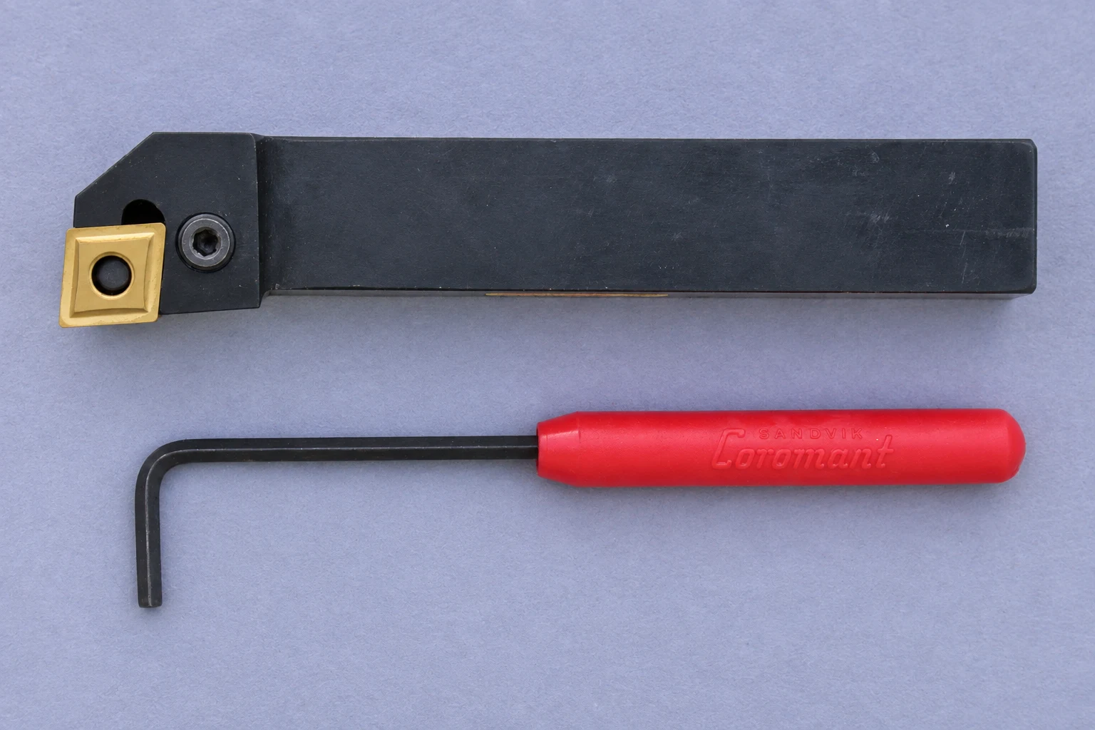

Quick answer: no, not as a direct replacement
A CCMT insert should not be fitted to a CNMG holder unless the holder manufacturer explicitly lists that exact insert designation as compatible. Both codes begin with C, so both inserts have an 80° rhombic shape. That shared outline does not make the pocket interface the same. In the second code position, N means 0° clearance and C means 7° clearance. The seat, support surfaces, size, thickness, centre hole, countersink and clamping system must all match.
If a CCMT insert appears to sit inside a CNMG pocket, that is still not proof of safe or accurate fit. Confirm the complete insert code and complete holder code before machining.
Why the shared “C” causes confusion
ISO 1832 provides a designation system for indexable inserts. In a code such as CNMG or CCMT, each position describes a different feature. The first letter is the insert shape. Here, C identifies an 80° rhombic insert. It does not describe the relief beneath the cutting edge, dimensional tolerance, hole style or clamping arrangement.
That is why a buyer comparing only the first letter can reach the wrong conclusion. CNMG and CCMT can look related from above because their nominal corner angle is the same. The holder, however, supports and locates the insert in three dimensions. Compatibility depends on the complete interface, not the top-view silhouette.
The first four letters are a sequence, not a product name
For common turning inserts, the early code positions describe shape, clearance angle, tolerance class and insert type. The following numbers normally identify nominal size, thickness and nose radius according to the applicable designation convention. Chipbreaker, edge preparation, substrate and coating may then appear as manufacturer-specific suffixes.
So “CCMT” and “CNMG” identify geometry families. Neither is a complete purchasing specification. A useful cross-reference starts with the full code printed on the insert box and the full designation marked on the holder.
The clearance angle changes the holder interface
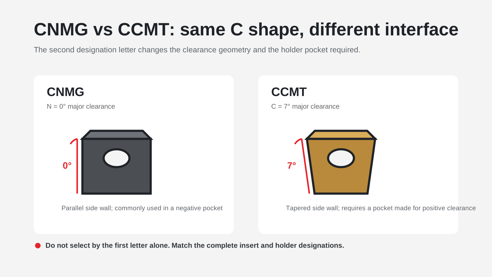
CNMG: 0° clearance and negative geometry
The N in CNMG denotes a 0° major clearance angle. The insert side is nominally perpendicular to its top and bottom faces. A matching negative-style holder pocket is designed to support this geometry at the required cutting orientation. This family is widely used where a strong cutting corner and a robust insert-seat relationship are important, but the correct application still depends on holder style, approach angle, material, chipbreaker and cutting conditions.
CCMT: 7° clearance and positive geometry
The C in the second position of CCMT denotes a 7° major clearance angle. The tapered side geometry creates relief behind the cutting edge when the insert is mounted in the intended positive-style pocket. Official manufacturer product data for CCMT examples lists an 80° included angle and 7° major clearance, while CNMG examples list an 80° included angle and 0° major clearance.
Why “it fits in the pocket” is not enough
A pocket can appear large enough while failing to support the insert on the intended locating faces. Incorrect contact can change edge height, rake presentation and clamping load. It can also allow the insert to rock or concentrate force on a small area. The reliable test is not whether the screw can be tightened; it is whether the holder specification names the insert family and size.
Six checks before matching an insert to a holder
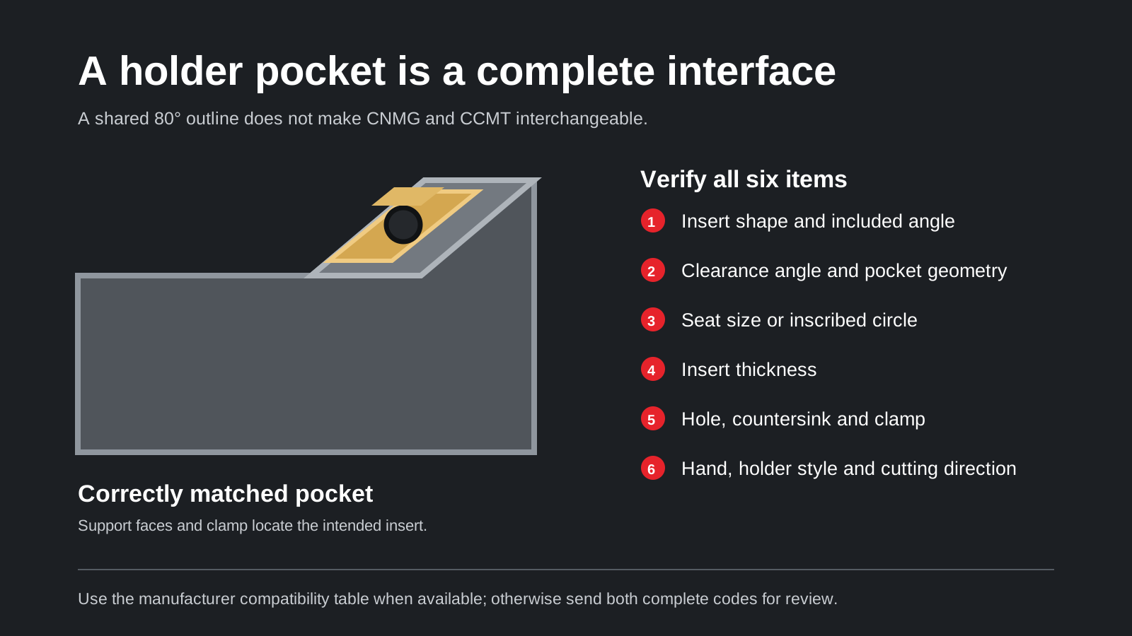
Use the complete designations and a manufacturer compatibility table wherever one is available. When a code, box or tool mark is incomplete, check these six interface points before requesting an alternative.
1. Shape and included angle
The first letter must agree with the pocket’s intended shape. CNMG and CCMT both use the C shape, but this is only the first check. A matching outline cannot override differences elsewhere in the code.
2. Clearance angle
The second letter must agree with the holder’s seat and cutting orientation. N and C are not interchangeable labels: they represent 0° and 7° clearance respectively. This is the central reason a normal CCMT insert is not a drop-in replacement for a CNMG insert.
3. Nominal size and thickness
The numerical positions identify dimensions such as insert size and thickness under the relevant code convention. Two C-shaped inserts can have different edge lengths, inscribed-circle relationships or thicknesses. A mismatch can put the cutting edge in the wrong position or prevent full seating.
4. Hole, countersink and clamping method
The fourth letter and the detailed manufacturer drawing help identify the insert type and clamping features. Centre-hole diameter, countersink form, lever engagement, top clamp and screw arrangement matter. A screw passing through a hole is not the same as the correct clamping interface.
5. Pocket seat and support faces
Inspect the pocket, shim and locating walls. The insert should contact the surfaces intended by the holder design without rocking, visible gaps or improvised packing. Damaged shims and worn pocket walls can also create apparent compatibility problems even when the codes are correct.
6. Nose radius, hand and cutting-edge position
Nose radius affects tool offset, profile clearance and cutting behaviour. Holder hand and approach angle determine which corner reaches the workpiece. Confirm that the assembled cutting edge lands at the expected centre height and orientation; do not infer this from a loose insert placed in the pocket.
How the holder code helps
ISO 5608 establishes a designation system for turning and copying tool holders with rectangular shanks. Holder letters describe features such as clamping method, insert shape, holder style, insert clearance angle and hand. The exact sequence should be read against the applicable manufacturer or standard table rather than guessed from one familiar example.
MCLNR points to a CNMG-style negative insert system
In the common holder designation MCLNR, the letters identify a specific clamp and holder arrangement intended around a C-shaped insert with 0° clearance. This is why Vextrex lists MCLNR turning tool holders alongside CNMG turning inserts, subject to the complete size code and holder specification.
SCLCR is a familiar CCMT-style example
A common SCLCR holder designation identifies a different interface built around a C-shaped insert with 7° clearance. It is not the same pocket as MCLNR merely because both systems use an 80° insert outline. Always confirm the holder’s complete code, including shank size, insert-size position and hand.
| Check | CNMG family | CCMT family | Why it matters |
|---|---|---|---|
| Shape letter | C: 80° rhombic | C: 80° rhombic | Explains the similar top view, but not holder fit |
| Clearance letter | N: 0° | C: 7° | Changes the side geometry and intended pocket |
| Typical geometry | Negative | Positive | Affects support, presentation and cutting clearance |
| Common holder example | MCLNR family | SCLCR family | The complete holder code controls compatibility |
| Directly interchangeable? | No, unless the holder manufacturer explicitly specifies the exact alternative | Do not decide from outline or screw fit alone | |
What can happen with a forced mismatch?
An insert that is poorly supported can move under cutting load. Possible results include unstable dimensions, chatter, damaged screws or clamps, pocket deformation, unexpected edge fracture and loss of the workpiece. The severity depends on the machine, operation and load, but the core problem is avoidable: use the holder and insert combination documented for the system.
Do not machine an adaptor, grind the insert, omit a shim or use extra packing to make the parts appear to fit. Those changes alter the engineered clamping and support conditions. If the original holder code is unreadable, photograph the whole tool, pocket, shim, clamp and any remaining marks before ordering.
When should you choose CNMG or CCMT?
Choose from the job and the existing holder
If the machine already has a serviceable holder, start with its complete designation. Then match the insert family and size before selecting chipbreaker and grade. If you are specifying a new system, compare workpiece access, setup rigidity, operation type, cutting forces, finish requirement and usable machine envelope.
CNMG is often considered for robust general turning
CNMG’s negative geometry and strong 80° corner make it a common candidate for general external turning and facing in stable setups. That does not mean every CNMG variant is suitable for every roughing job. Chipbreaker, edge preparation, grade, coating and workpiece material remain application-specific.
CCMT is often considered where positive cutting action helps
CCMT’s 7° clearance is commonly used in positive-style turning and boring systems where access or a lower-force cutting action may be useful. Final selection still depends on the holder, material, depth of cut, feed, interruption and required finish. Use supplier data for the exact insert variant before setting cutting parameters.
For broader family selection, compare the turning insert range or use the ISO turning insert nomenclature guide to decode a complete insert designation.
What should you send for an accurate cross-reference?
You do not need to identify every code position yourself. A useful request can begin with one clear code or photo. To reduce back-and-forth, send:
- the full insert code from the box or laser mark;
- the full holder code and holder hand, if readable;
- clear photos of the insert top, side, underside and holder pocket;
- workpiece material and the turning operation;
- whether the cut is continuous or interrupted;
- required quantity and destination country.
Vextrex can compare the supplied code or images with suitable CCMT insert, CNMG insert and matching-holder options. Stock, price, grade, chipbreaker and lead time are confirmed for the exact specification in the quotation.
Frequently asked questions
Can a CCMT insert physically sit in a CNMG holder?
It may appear to enter some pockets because both families have an 80° C-shaped outline, but that does not establish correct support or cutting position. Treat it as incompatible unless the holder manufacturer explicitly approves the exact CCMT code.
Are CNMG and CCMT the same size?
No. The four-letter family code does not specify one size. The numerical positions that follow identify nominal dimensions, and those values must also match the holder specification.
What is the main difference between CNMG and CCMT?
The most important interface difference is the clearance angle: CNMG uses N for 0° clearance, while CCMT uses C for 7° clearance. They therefore belong to different negative and positive insert systems.
Can I identify the right insert from a holder photo?
Often a photo can narrow the options, especially when it shows the complete holder, pocket, clamp, shim and markings. A readable holder code is more reliable, and critical dimensions may still be required before quotation.
Standards and manufacturer references
- ISO 1832:2017, designation system for indexable inserts.
- ISO 5608:2012, designation system for turning and copying tool holders with rectangular shanks.
- Seco CCMT product data, including 80° included angle and 7° major clearance.
- Seco CNMG product data, including 80° included angle and 0° major clearance.
Always use the current drawing and compatibility table for the exact holder and insert being purchased. Standards explain the designation system; the manufacturer’s current product data controls the specific assembly.
Need help confirming the exact tool specification?
Send the model code, clear tool photos, workpiece material and machining task. We will review compatibility and application details before confirming available options, price and lead time.