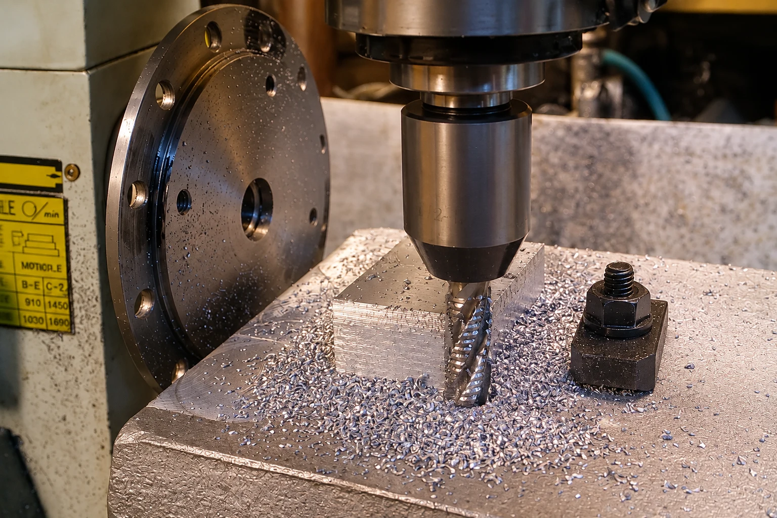

Quick answer: shorten and stiffen the system before chasing settings
Long-reach end mill chatter is a system problem, not only a speed problem. Begin with the shortest possible tool projection, a clean and suitable holder, rigid workholding and a toolpath that avoids sudden engagement. Then change one cutting variable at a time while recording the result.
Do not respond to every vibration by simply reducing feed. Excessively low chip load can cause rubbing and heat. The correct correction depends on whether the source is tool deflection, runout, holder balance, workpiece movement, corner engagement, recutting or an unstable spindle-speed zone.
Why long reach changes the cutting system
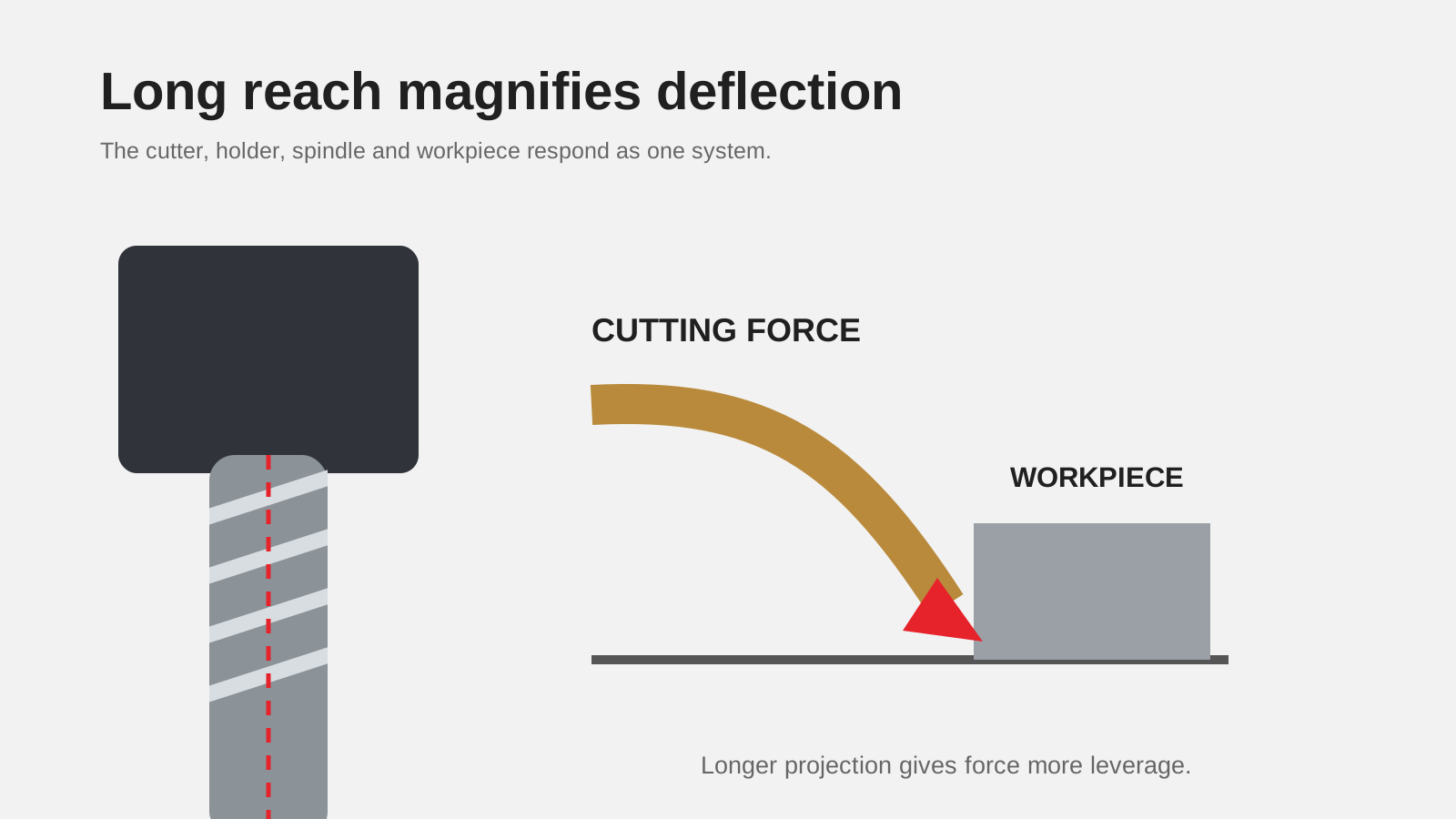
The cutting edge is loaded at the end of a projecting tool-holder assembly. Increasing projection gives cutting forces more leverage and reduces system stiffness. The workpiece, fixture, spindle, holder, collet and tool then behave as one dynamic system. A rigid machine cannot compensate for a loose workpiece, and a premium end mill cannot compensate for an unsuitable holder assembly.
Reach is not the same as flute length
Reach describes how far the tool must extend to access the feature. Flute length describes the cutting-edge length. Specifying both longer than necessary removes stiffness without adding useful capacity. A reduced-neck tool may provide clearance behind a shorter cutting length; whether it is suitable depends on the feature and manufacturer design.
Chatter can sustain itself
Once waviness left by one tooth changes the load on the next tooth, vibration can reinforce itself. Kennametal describes chatter as potentially self-sustaining and notes its effects on surface finish and end-mill life. This is why random small adjustments can appear inconsistent: they may move the system into or out of a stable operating region.
Diagnose the symptom before adjusting the program
Identify where chatter begins
Record whether the mark appears during entry, straight-wall cutting, a corner, a floor pass or exit. Corner engagement can increase the number of teeth in the cut and raise forces abruptly. A problem isolated to one region points toward toolpath or local workpiece stiffness rather than a universal tool failure.
Inspect the frequency and direction of marks
Regular waves on a wall, vibration on the floor and a squeal during a specific move are different clues. Photograph the surface and record the toolpath direction. If possible, compare the same cut at a different axial level to see whether tool deflection or fixture support changes.
Check the tool before reusing it
Chipping, uneven wear, packed flutes or a damaged corner can create vibration even after the original cause is removed. Replace a compromised tool before using the next trial to judge a process change.
Rigidity checks with the highest practical value
Use the shortest overhang that clears the feature
Kennametal lists short overhang and stub-length tools among the better first steps for improving stability. Measure projection from the holder face to the tool tip and record it with the setup. Do not clamp on flutes or transition radii.
Review holder, collet and assembly condition
Clean the spindle taper, holder, collet and tool shank. Inspect contact surfaces for fretting or damage. Confirm that the holder style is appropriate for the speed, reach and operation. A balanced holder helps, but balance does not correct runout, contamination or poor clamping.
Strengthen the workpiece support
Move clamps closer to the cut when possible, reduce unsupported workpiece length and avoid loading a thin wall in its flexible direction. Reprogramming the cut so force enters the stiffer part of the workpiece can be more effective than changing the end mill.
Control engagement and toolpath
Avoid sudden corner loading
When a cutter enters an internal corner, radial engagement can rise sharply. Use a toolpath that maintains a more consistent engagement where the part geometry allows. A larger programmed corner radius followed by a smaller cleanup tool is one documented approach, but the drawing and process plan must permit it.
Reduce the load without creating rubbing
Lowering radial or axial engagement reduces cutting force. That is different from blindly reducing feed per tooth. Maintain an actual chip and use the exact tool supplier’s data as the starting point. If recutting is visible, improve chip evacuation before judging the new setting.
Use a larger or stronger tool where access permits
A larger diameter or core section can improve stiffness, but only if the feature, holder, spindle and corner radius allow it. If access fixes the diameter, consider a tool designed specifically for long reach rather than extending a standard tool beyond its intended setup.
Adjust cutting data methodically
Change one variable per trial
Record spindle speed, feed, axial depth, radial engagement, tool projection and result. Changing several inputs together prevents you from learning which change moved the system. A controlled speed change may find a more stable zone; a controlled engagement change may reduce excitation.
Do not publish one universal reduction percentage
The correct change depends on tool diameter, flute count, helix, holder, spindle, material and engagement. There is no responsible universal percentage for every long-reach setup. Use the manufacturer’s product data and validate under safe, controlled conditions.
Watch machine and holder limits
Do not exceed maximum speed, clamping or balance limits in an attempt to escape chatter. Confirm that the programmed feed is within the machine’s acceleration capability, especially in short segments and corners.
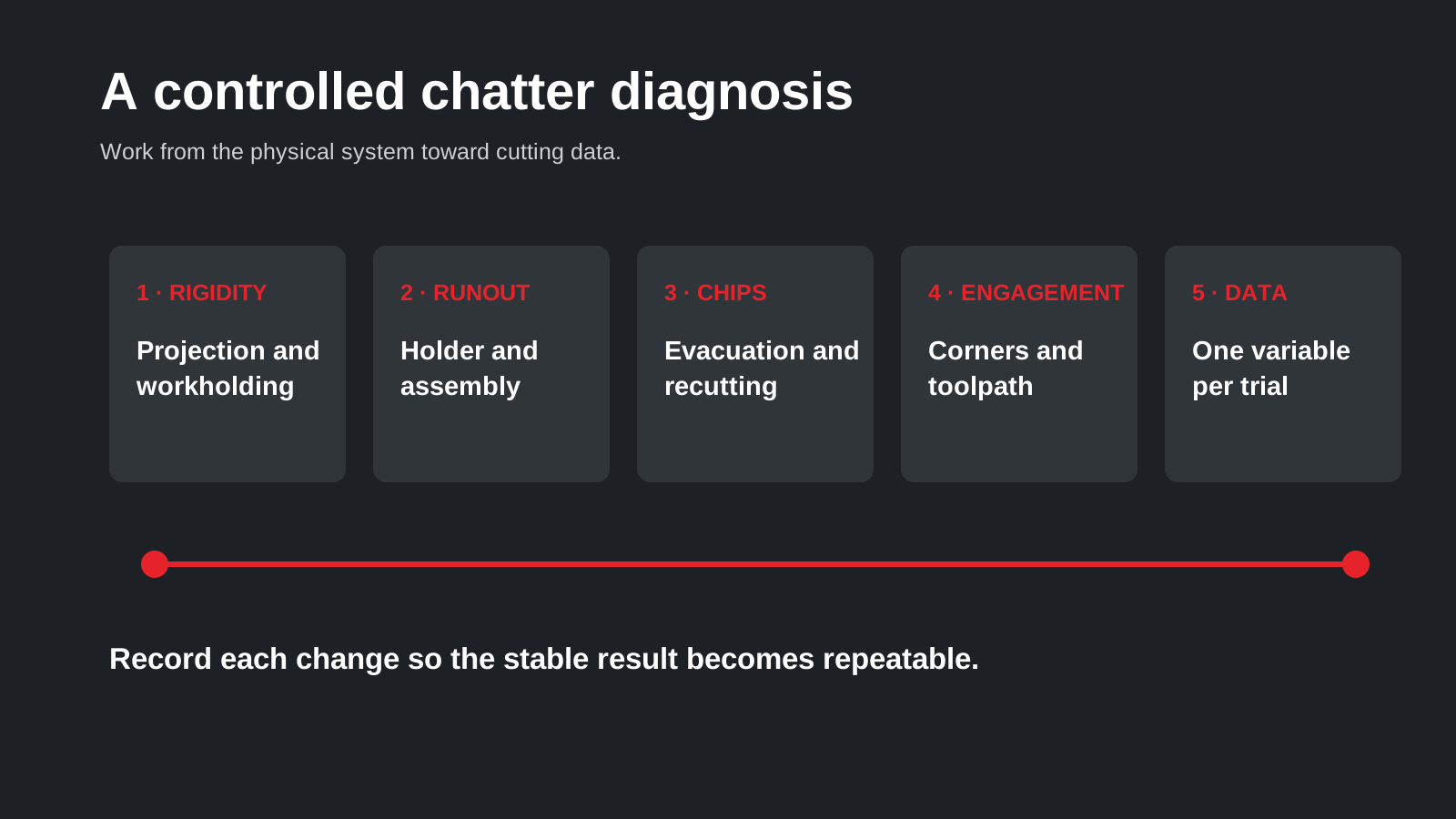
A repeatable troubleshooting order
- Stop and inspect the cutting edges and machined surface.
- Record tool projection, holder, collet, runout check and workholding.
- Shorten projection or improve support if possible.
- Confirm chip evacuation and eliminate recutting.
- Locate engagement spikes in the toolpath.
- Reduce radial or axial engagement where appropriate.
- Change one speed or feed variable using verified tool data.
- Document the stable result for the repeat order.
For tool selection, compare the long-reach 4-flute end mill with the shortest standard 4-flute flat end mill that can access the feature.
What to send for a chatter review
Provide workpiece material, tool diameter, flute count, cutting length, projection from holder, holder and collet, spindle speed, feed, axial and radial engagement, coolant method, toolpath screenshot and photos of the surface and worn tool. A short video with sound can also help locate when vibration starts.
Vextrex can review the setup and compare practical tool geometries. Any proposed cutting values must be tied to the exact selected tool and confirmed against machine and process limits.
Separate access requirements from habit
Many setups use a long tool because the previous job used one, not because the current feature requires it. Mark the actual obstruction on the drawing and calculate the minimum neck clearance and projection. A shorter standard tool for open regions plus a long-reach tool only for the obstructed region can be more stable than forcing one tool to complete the entire part.
Create a repeatable trial record
Give each test a unique line containing the tool code, measured projection, holder assembly, work offset, cutting data and result. Add a photograph of the surface at the same lighting angle. This turns chatter correction into controlled process development and prevents a successful setting from disappearing at the next setup.
Frequently asked questions
Should I reduce spindle speed first?
Not automatically. Check projection, holder condition, workholding, engagement and chip evacuation first, then change one cutting variable at a time.
Does a longer flute length solve a deep-reach problem?
Not necessarily. Use only the cutting length required and distinguish flute length from reach so unnecessary flexibility is not added.
Can runout cause chatter?
Yes. The tool, collet, holder, spindle taper and assembly cleanliness can contribute to runout and uneven flute loading.
Can one chatter setting work on every machine?
No. Stability belongs to the complete tool-holder-spindle-workpiece system.
Manufacturer reference
Use manufacturer recommendations for the exact product and validate changes within machine, holder and workholding limits.
What not to do when chatter starts
Avoid extending a standard tool farther without checking the intended setup, slowing feed until the edge rubs, or changing speed, feed and engagement in one trial. Each shortcut can hide the original problem and make the next result harder to interpret.
Also separate feature access from habit. Mark the actual obstruction on the drawing and determine the minimum neck clearance and projection. A short tool for open regions plus a long-reach tool only for the obstructed region may be more stable than forcing one extended tool to finish the whole part.
If the setup cannot be made sufficiently rigid, revise the process plan. Persistent noise, changing surface waves or repeated corner chipping are not acceptable merely because the part still reaches nominal size.
Need help confirming the exact tool specification?
Send the model code, clear tool photos, workpiece material and machining task. We will review compatibility and application details before confirming available options, price and lead time.