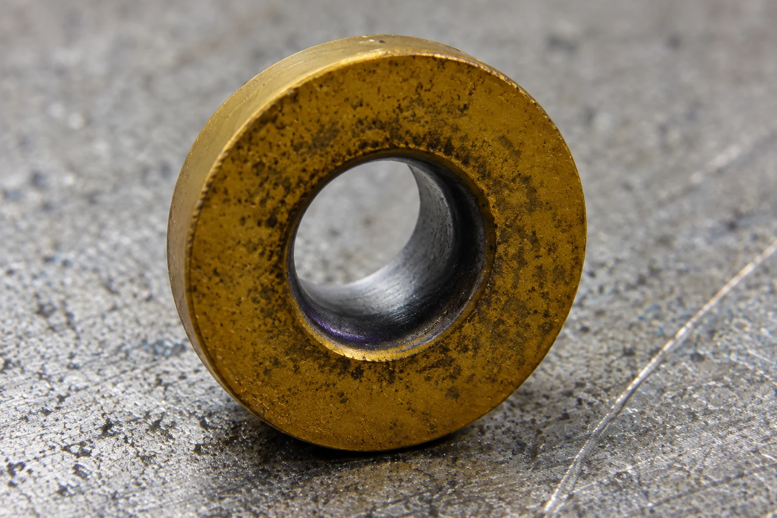
.jpg)
Quick answer: a grade is a package of substrate, coating and edge preparation
Select the carbide substrate for the required balance of toughness and wear resistance. Select coating technology and composition for the workpiece, temperature and dominant wear mode. Select edge preparation for cutting force, interruption and finish. These layers must be evaluated together.
Do not cross-reference grades from colour, a short marketing label or one ISO material letter. Similar-looking inserts can use different carbide grain structures, binders, coating stacks and honed edges.
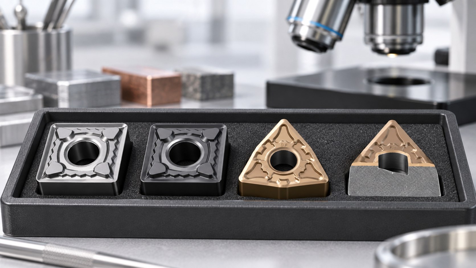
Three selection layers that should not be collapsed into one
| Layer | Primary role | Application evidence |
|---|---|---|
| Carbide substrate | Supports toughness, hardness and deformation resistance | Stability, interruption, temperature and wear pattern |
| Coating | Changes friction, heat flow, chemical and abrasive wear behaviour | Material group, cutting speed, coolant and wear mode |
| Edge preparation | Changes local support, sharpness and cutting force | Feed, depth, finish, burr and chipping risk |
| Chipbreaker geometry | Controls chip formation and supports the edge over a working range | Operation, feed, depth and chip result |
A supplier’s grade code may package several of these decisions, but the code itself is not portable proof. Keep the complete insert designation and application record.
Carbide substrate: balance wear resistance and toughness
Wear-resistant choices need a stable process
A harder, more wear-resistant substrate can perform well in continuous, rigid cuts. If the process contains impact, chatter, poor seating or heavy interruption, that same edge may chip before its wear resistance becomes useful.
Tough choices are not automatically slow
A tougher grade can improve edge security, but excessive plastic deformation or rapid flank wear indicates that temperature and wear resistance also need attention. The correct balance depends on the complete cutting condition.
Grain size and binder are controlled material variables
Carbide is not one uniform material. Grain structure, binder content and manufacturing control influence behaviour. These details may not be visible in a commercial grade name, which is why supplier evidence and application validation matter.
PVD and CVD coatings: use process context, not a simple ranking
PVD-coated grades
Physical vapour deposition coatings are commonly used where a relatively sharp edge, toughness and controlled coating thickness are valuable. Many finishing, threading, grooving and difficult-material applications use PVD-coated grades, but the coating composition and substrate still determine the actual operating range.
CVD-coated grades
Chemical vapour deposition coatings are widely applied for wear resistance at productive cutting conditions, especially in suitable turning applications. A CVD grade is not automatically the best roughing grade, and a PVD grade is not automatically the best finishing grade. The cut and edge package decide.
Uncoated carbide remains a deliberate option
Uncoated, sharp-edged carbide can be appropriate for some non-ferrous or low-speed applications. It should be selected because the edge and material benefit, not because coating colour is absent.
| Condition | Question | Risk if ignored |
|---|---|---|
| High temperature | Is heat concentrated at the edge or carried by the chip? | Crater wear, deformation or coating breakdown |
| Interrupted cut | How severe and frequent is the impact? | Edge chipping or coating delamination at a weak edge |
| Adhesive material | Is the rake surface smooth enough to resist build-up? | Built-up edge and unstable finish |
| Abrasive skin | Does scale or hard inclusion contact one line repeatedly? | Rapid flank or notch wear |
Edge preparation can change the result before the coating does
Sharp edges
A sharp edge reduces cutting force and supports fine finishing or soft, adhesive materials. It is also less supported against impact. Runout and handling damage become more important.
Honed edges
A controlled hone strengthens the edge and changes chip contact. Too much hone for the feed and material can increase ploughing, heat and burr formation.
Chamfers and reinforced lands
A chamfer can support heavy loads and interruption when its width and angle fit the application. It also increases cutting force. Do not copy a reinforced edge into a flexible component without reviewing deflection and finish.
The edge preparation is often embedded in a supplier chipbreaker or geometry suffix. Preserve it in repeat orders rather than ordering only the base family and grade.
Let the wear mode guide the next trial
- Uniform flank wear: record progression; it can be a controllable end-of-life mode.
- Crater wear: review temperature, speed, coating and chip contact.
- Edge chipping: check impact, runout, interruption, grade toughness and edge support.
- Plastic deformation: review heat, substrate strength, speed and edge load.
- Notch wear: inspect work-hardened or abrasive surface at the depth-of-cut line.
- Built-up edge: review adhesion, edge finish, speed, lubrication and chip recutting.
Use macro photographs taken at consistent intervals. “Tool life was poor” is less useful than a visible wear pattern after a known number of parts or minutes.
How to cross-reference a supplier grade responsibly
- Match the complete geometry and dimensions first.
- Record the workpiece standard, hardness and operation.
- Identify the current wear mode rather than relying only on stated tool life.
- Compare the proposed substrate, coating route and edge preparation using supplier data.
- Run a controlled sample with the same holder, material and inspection method.
- Approve or reject the exact variant; do not approve a colour or broad product family.
A cross-reference is a testable proposal, not a declaration of equivalence. Different suppliers can reach similar application goals with different material packages.
Before comparing grades, decode the base insert using the ISO turning insert nomenclature guide and select the shape using the turning insert family comparison.
Minimum approval and repeat-order record
| Record | Purpose |
|---|---|
| Full insert designation | Preserves family, size, chipbreaker and grade |
| Supplier and batch | Supports traceability when performance changes |
| Material and operation | Prevents approval from being applied to a different job |
| Cutting conditions | Makes the trial repeatable |
| Wear and inspection evidence | Separates fit from process performance |
| Commercial terms | Keeps technical approval separate from price and lead time |
Frequently asked questions
Can coating colour identify the coating?
No. Confirm the written coating and complete grade designation.
Is a harder grade always longer lasting?
No. A wear-resistant grade can chip early in an unstable or interrupted cut.
Are supplier grades with similar descriptions interchangeable?
Not automatically. Substrate, coating architecture and edge preparation can differ, so validate a sample.
What should be recorded after approval?
Keep the full code, supplier, batch, holder, material, cutting conditions and accepted inspection result.
Manufacturer references
Need help confirming the exact tool specification?
Send the model code, clear tool photos, workpiece material and machining task. We will review compatibility and application details before confirming available options, price and lead time.