
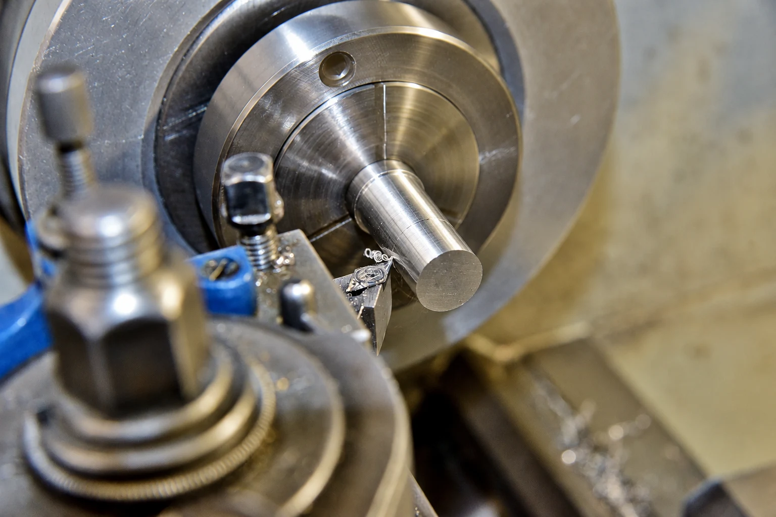
A chipped insert can stop a stainless steel job before the operator reaches the planned tool change. Replacing the edge without checking the cause often repeats the failure. Carbide insert chipping in stainless steel needs a short diagnostic sequence: identify the damage, verify the setup, then test a specific change.
This guide is for a shop trying to recover a turning operation, not choose a universal cutting speed. Keep the rejected insert, photograph its working edge and record the complete tool code before anything goes into the scrap bin.
1. Diagnose Carbide Insert Chipping in Stainless Steel
Inspect the edge under suitable magnification after safely stopping the machine. Actual chipping leaves missing carbide. Built-up edge deposits workpiece material on the cutting edge and can disguise the underlying damage. Localized notching near the depth-of-cut line needs separate attention from damage spread along the edge. Seco’s stainless steel wear guide explains these distinctions.
Ask the operator when the problem starts. Damage on entry into a cross-hole suggests a different investigation from damage after a long, uninterrupted pass. A change after a new material batch also deserves investigation before changing the insert supplier.
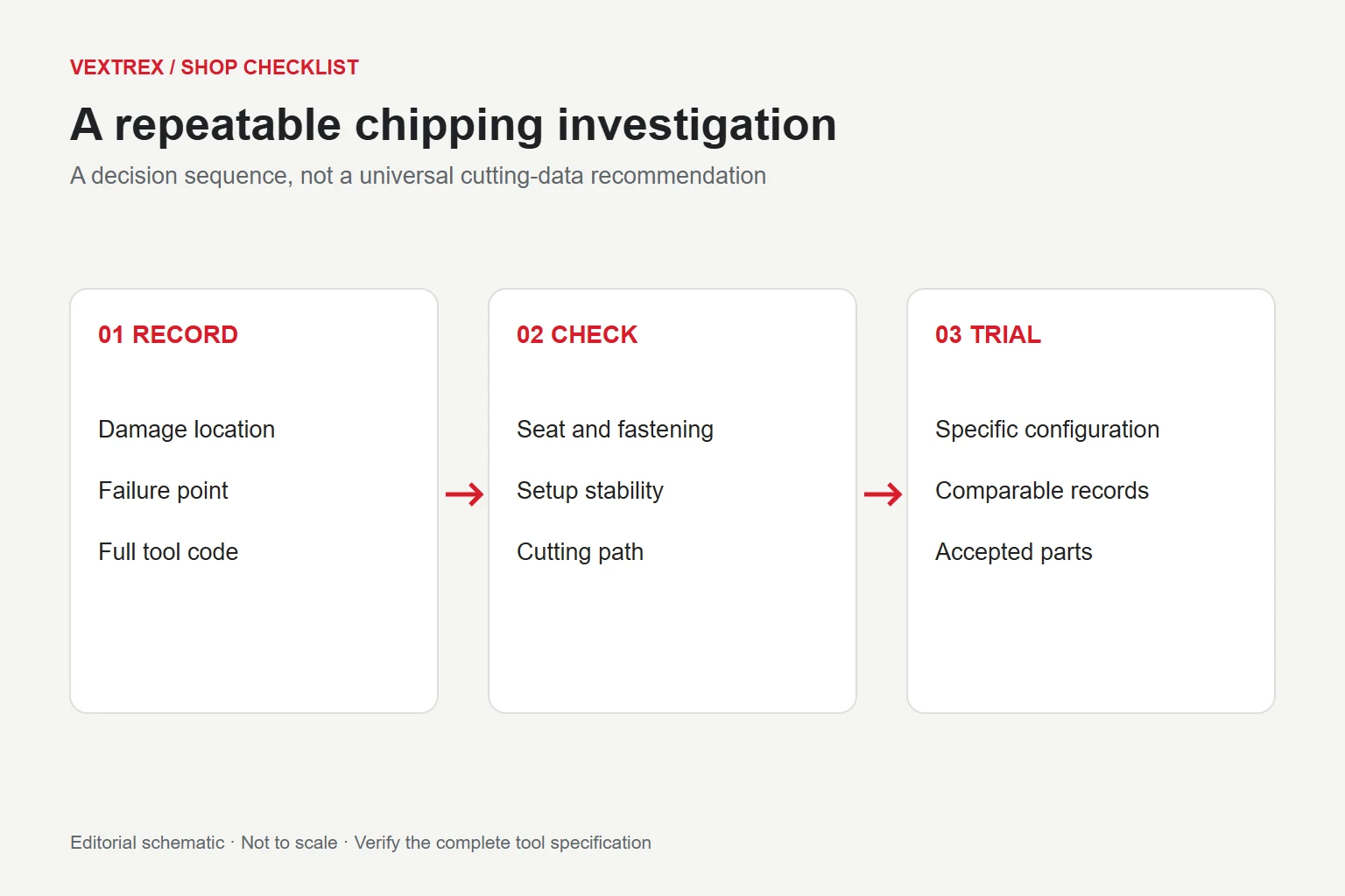
Write down four observations:
- Where is the damage: corner, main edge or depth-of-cut line?
- When does it appear: entry, steady cutting, exit or after indexing?
- What accompanies it: chatter marks, chip wrapping, size drift or poor finish?
- What changed: material batch, holder, program, coolant or insert specification?
Do not diagnose grade toughness from coating color. Photograph the box label as well as the damaged edge. A stainless steel designation such as 304 or 316 is useful, but material condition and the actual operation still matter.
2. Check the Seat, Clamping and Cutting Path
With the machine stopped and tooling handled according to the shop’s procedure, inspect the pocket, shim and fastening parts. Remove debris without damaging the seating surfaces. Check for damaged contact areas and use the holder manufacturer’s tightening instructions rather than increasing torque until the insert seems secure.
Check tool projection, workpiece support and centre height where applicable. Do not buy a tougher insert to compensate for a visibly damaged seat or a moving workpiece. Sandvik’s turning handbook identifies instability, excessive projection and unsuitable geometry among chipping checks.
Review the program at the actual failure location. Look for an interrupted feature, entry into remaining stock, a shoulder transition or an unexpected allowance. Compare the programmed operation with what the casting, bar or previous operation actually leaves.
Check coolant delivery at the cutting zone using the machine’s approved inspection procedure. Record whether flow changes during the cycle. Keep this condition documented during the trial instead of changing it alongside the grade, feed and geometry.
Before ordering another family, compare the complete designation and holder requirements on the CNMG turning insert page. A matching outline is not confirmation of an approved tool assembly.
3. Run a Controlled Cutting and Grade Trial
Do not automatically slow everything down. Austenitic stainless steel can work harden, and unsuitable conditions may encourage rubbing or built-up edge. Review the exact insert manufacturer’s feed, speed and depth-of-cut guidance; reducing feed below its intended working range is not a universal cure.
Separate the decisions. A chipbreaker controls the working geometry; the grade provides its own combination of substrate, coating and edge preparation. Ask the supplier which change addresses the observed failure instead of accepting “stainless grade” as a complete specification.
Use a simple trial plan:
- Record the current insert, holder, material, cutting conditions and failure point.
- Correct any verified seating or setup problem first.
- Select one candidate geometry or grade with application guidance.
- Run the agreed comparison and inspect at consistent intervals.
- Record edge damage, acceptable parts, dimensional results and why each run stopped.
Do not deliberately repeat an unsafe failure merely to establish a baseline. Use existing production records if the original condition risks tooling or equipment damage. Record any necessary process changes so the comparison remains interpretable.
Kennametal’s turning troubleshooting guidance also treats edge damage as a process problem requiring identification before correction.
If another holder system is genuinely worth evaluating, review WNMG turning insert options and our WNMG vs CNMG selection guide. Do not change the insert outline without a compatible holder and program review.
For mixed-material shops, the companion cast iron grade selection guide shows why a grade recommendation should follow the workpiece and operation, rather than become a blanket rule for every job.
4. Frequently Asked Questions
Should I lower cutting speed whenever an insert chips?
Not without identifying the failure. Heat-related damage, built-up edge and mechanical impact require different checks. Use the exact manufacturer’s application guidance and record the outcome of each adjustment.
Will a larger nose radius solve the problem?
Not automatically. It changes the working edge and force balance. Check the component profile, depth of cut and setup stability before changing radius.
Can I keep the holder and replace CNMG with WNMG?
Only if the holder documentation explicitly approves that complete insert configuration. Similar corner angles do not make the pockets interchangeable.
Summary
Identify the damage, eliminate verified setup faults and trial a documented geometry or grade. Judge the result by repeatable acceptable parts, not one undamaged edge after a short cut.
Request a sample or quotation. Send Vextrex the complete insert and holder codes, stainless alloy, operation, cutting conditions, damage photos, quantity and destination. Standard carbide insert samples are free, supplied as one complete box of 10; the buyer pays destination-based freight, confirmed after inquiry. Start with our CNMG model references or WNMG model references and identify the exact sample configuration.
Technical sources
Need help confirming the exact tool specification?
Send the model code, clear tool photos, workpiece material and machining task. We will review compatibility and application details before confirming available options, price and lead time.