
Quick answer: select diameter and depth together
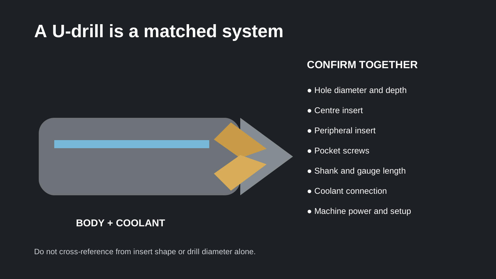
A U-drill is not selected by hole diameter alone. Define the finished-hole diameter and required depth, convert the depth to a diameter ratio such as 2×D, 3×D or 5×D, then confirm the body length, insert pocket, shank, coolant supply and machine capacity. The same nominal diameter can be available in more than one depth series.
Published ranges are product-family specific. For example, Sandvik’s CoroDrill 880 documentation lists 12–63.50 mm for one referenced range and depth options from 2×D to 5×D under stated configuration limits. Do not treat those values as universal dimensions for every U-drill.
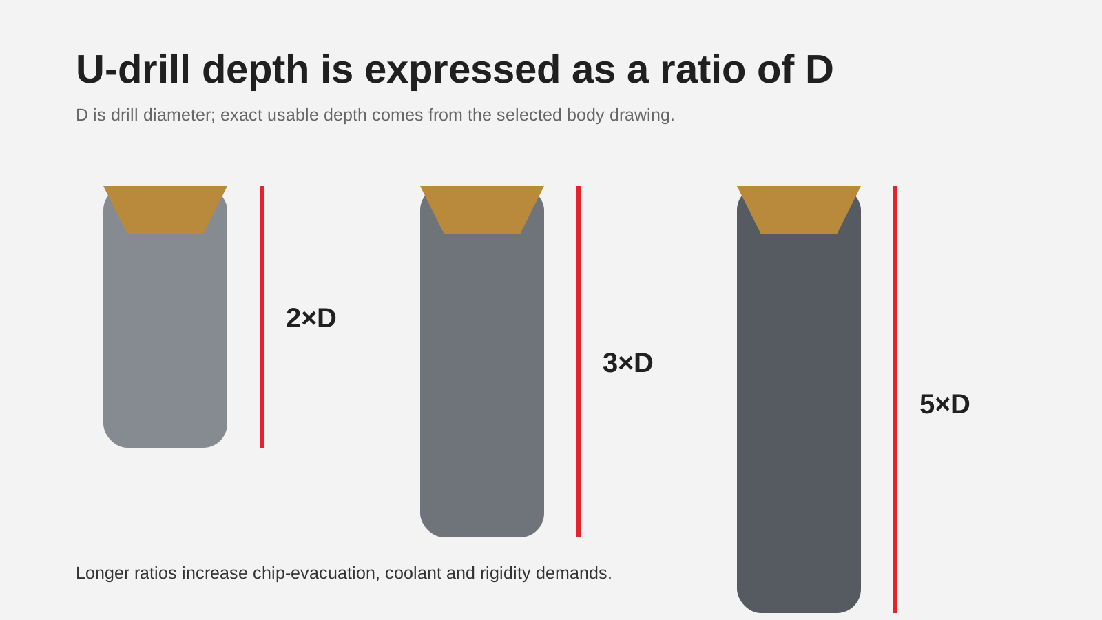
How to read 2×D, 3×D and 5×D
D represents the drill diameter. A nominal 3×D body is designed around a drilling depth of approximately three times its diameter. For a 20 mm drill, 3×D describes roughly 60 mm of nominal depth. The exact usable depth, flute length, point geometry and programming length must come from the body drawing.
Depth ratio is not overall length
Overall length includes shank and body portions outside the hole. Do not order from overall length when the application requires a specific drilling depth. Send the required hole depth and any fixture or shoulder clearance separately.
More depth increases evacuation demand
As the hole becomes deeper, chips travel farther along the flute and coolant delivery becomes more important. A body long enough to reach the bottom is not automatically capable of evacuating chips in the actual material and setup.
Breakthrough and blind holes need different details
For a blind hole, define bottom geometry and usable cylindrical depth. For a through hole, state the breakthrough condition and clearance behind the workpiece. An angled or interrupted exit can load the inserts unevenly.
How diameter range affects the body and inserts
Standard ranges differ by manufacturer
A published range belongs to a defined product family, catalogue generation and coupling option. Sandvik’s documentation is useful evidence that indexable U-drill systems can cover a broad range, but it is not a substitute for the Vextrex quotation record or another manufacturer’s current catalogue.
Diameter adjustment is limited and controlled
Some systems support controlled diameter adjustment with specific sleeves or offset settings; others do not. Never assume a body can be offset to any nearby diameter. Check the manufacturer’s permitted adjustment and the effect on hole quality and insert loading.
Special diameters may require a different body
A non-standard hole may be better served by a special body, boring operation or another drill concept. State tolerance and downstream finishing so the quotation does not solve only the nominal diameter while missing the process requirement.
Match the centre and peripheral inserts correctly
The two pockets do different work
Many indexable drills use a centre insert and a peripheral insert. They see different cutting speeds and loads. Even when the inserts share a base shape such as WCMX or SPMT, pocket position and manufacturer recommendation control placement.
Insert size and screw must match the body
Confirm the body code, insert code, screw and pocket condition. A similar-looking WCMX U-drill insert or SPMT drilling insert should not be installed from appearance alone.
Grade and geometry follow the material
After physical fit is confirmed, select substrate, coating and chip geometry for the workpiece, interruption, coolant and required reliability. Keep the approved insert position and grade in the repeat-order record.
Machine and setup checks before ordering
Shank and available tool length
Specify shank diameter and style, turret or spindle interface, gauge-length limit and nearby interference. A correct drill diameter is unusable if the shank cannot be held or the body collides with the fixture.
Coolant delivery
State internal or external coolant, available pressure and whether coolant reaches the cutting zone throughout the depth. Do not copy a parameter chart that assumes through-coolant when the machine cannot supply it.
Power, torque and rigidity
Large diameter and high feed increase demand on the spindle and setup. Confirm machine limits, workholding and entry surface. On a lathe, state whether the drill rotates or remains stationary and whether alignment has been checked.
Hole quality and secondary operations
An indexable drill can produce useful production holes, but the required diameter tolerance, straightness, position and finish decide whether the hole is complete. Manufacturer literature for one product family does not guarantee the same tolerance on a different body, material or machine.
Define the actual requirement
State whether the hole is clearance, pre-bore, tapping preparation, bearing fit or hydraulic passage. A loose clearance hole and a finished bearing bore should not receive the same process recommendation.
Plan boring or reaming when required
If the tolerance or finish is tighter than the drilling system can reliably hold, leave controlled stock for a secondary tool. This is a process decision, not evidence that the drill failed.
What to send for a U-drill quotation
- hole diameter, depth and tolerance;
- blind or through hole, entry and exit condition;
- workpiece material and hardness where known;
- machine type, spindle or turret interface and shank requirement;
- internal-coolant availability;
- current drill body and insert codes, if replacing a system;
- quantity for body, inserts and spare screws.
Browse carbide drilling tools or send a drawing. Vextrex will confirm the exact body, insert positions, stock, price and lead time before order acceptance.
Separate the nominal hole from the finished feature
A drawing may call for a counterbore, chamfer, cross-hole or flat-bottom region in addition to the drilled diameter. Mark which features the U-drill must produce and which will be finished later. This prevents a quotation for a standard body when the application actually needs a special tool or a second operation.
State entry and exit surfaces
Curved, cast, angled or flame-cut entry surfaces can load one side of the drill before the other. A cross-hole or angled breakthrough can do the same at exit. Send a section view and describe interruptions so the body, insert geometry and process plan can be reviewed together.
Plan consumables with the body
A useful first order includes the body, correctly positioned centre and peripheral inserts, spare screws and any required driver or adjustment component. Record which grade belongs in each pocket. Mixing positions during maintenance can create uneven load even though both inserts physically fit.
| Input | Selection effect |
|---|---|
| Diameter and tolerance | Body range and possible finishing operation |
| Depth ratio | Body series, evacuation and coolant demand |
| Entry and exit | Insert loading and process strategy |
| Machine interface | Shank, gauge length and available power |
Frequently asked questions
What does 3×D mean on a U-drill?
It describes nominal drilling depth of approximately three times drill diameter. Use the exact body drawing for usable depth.
Can one WCMX insert fit every U-drill?
No. Match body pocket, insert size, position, screw and manufacturer specification.
Does a U-drill produce a finished hole?
It may, but required tolerance, straightness and finish determine whether boring or reaming is still needed.
Can I select from hole diameter alone?
No. Depth, entry, exit, shank, coolant, machine, setup and material also matter.
Manufacturer reference
- Sandvik Coromant, CoroDrill 880 documentation, including the referenced 12–63.50 mm and 2×D–5×D configuration range.
Ranges are cited as a manufacturer example, not as a universal Vextrex stock claim.
Approve the complete drilling system
Before production, verify body runout or alignment using the machine builder’s and drill manufacturer’s procedure. On a stationary drill in a lathe, turret alignment can affect centre and peripheral inserts differently. On a rotating setup, the holder and spindle interface become part of the same check.
Inspect the first holes using the method required by the drawing. Record diameter, position, straightness and finish where applicable, then inspect both insert positions for unequal wear. If one position fails early, investigate alignment, grade selection, evacuation and entry condition rather than replacing both inserts blindly.
When depth approaches the limit of a body series, confirm that chips can exit in the actual material. A longer body may be available but less reliable than a shorter drilling step followed by another operation. The right choice minimizes total process risk, not merely the number of tools used.
Need help confirming the exact tool specification?
Send the model code, clear tool photos, workpiece material and machining task. We will review compatibility and application details before confirming available options, price and lead time.