
Quick answer: the calculator converts verified inputs; it does not choose them
Enter drill diameter in millimetres, cutting speed in metres per minute and feed per revolution in millimetres per revolution. The calculator returns spindle speed and linear feed rate. Cutting speed and feed must come from current data for the exact U-drill body, centre and peripheral inserts, workpiece and setup.
Before trial cutting, compare the result with spindle-speed, feed, power, coolant and tool-overhang limits. A mathematically correct result can still be unsafe for the machine or unstable for the application.
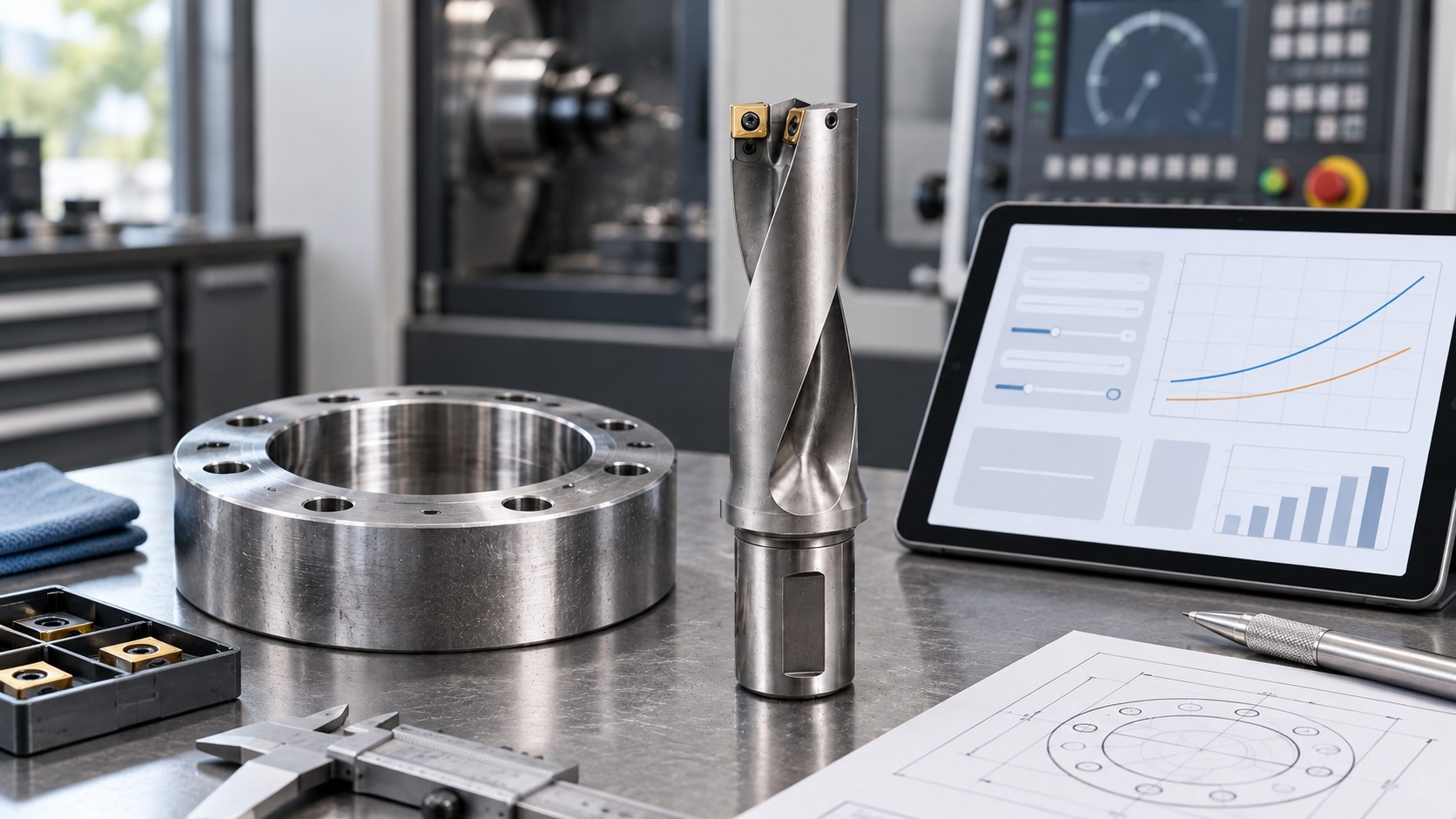
U-drill spindle-speed and feed-rate calculator
This tool uses metric units. It converts verified inputs and does not recommend cutting data.
Formulas and units
For metric drilling calculations:
- Spindle speed: n = (vc × 1000) ÷ (π × Dc)
- Feed rate: vf = fn × n
| Symbol | Meaning | Metric unit |
|---|---|---|
| Dc | Drill diameter | mm |
| vc | Cutting speed | m/min |
| fn | Feed per revolution | mm/rev |
| n | Spindle speed | r/min |
| vf | Linear feed rate | mm/min |
Do not enter surface feet per minute into the metric cutting-speed field or inches into the diameter field. Unit errors can change the result by a large factor while still producing a plausible-looking number.
Where the input values must come from
Drill diameter
Use the nominal cutting diameter of the selected drill body, not shank diameter or the measured pilot mark. If an adjustable or special body is involved, use its approved setting and drawing.
Cutting speed
Use the manufacturer’s starting range for the exact insert grade, geometry and workpiece condition. Centre and peripheral inserts can experience different cutting conditions, so the recommended system data matters.
Feed per revolution
Use the drilling feed definition supplied for the selected body and inserts. Do not substitute a milling feed per tooth or a turning value with the same unit symbol.
Body and insert matching
Before calculating, confirm the pocket, centre insert, peripheral insert, screws and body size. Read the U-drill diameter and depth guide and review WCMX U-drill inserts, SPMT drilling inserts and carbide drilling tools at model level.
Worked conversion example
Assume a verified application sheet provides a 25 mm drill diameter, 100 m/min cutting speed and 0.10 mm/rev feed. The equations give approximately:
- n = (100 × 1000) ÷ (π × 25) ≈ 1273 r/min;
- vf = 0.10 × 1273 ≈ 127 mm/min.
This example demonstrates unit conversion only. It is not a recommendation for any material, insert or machine. Round only after calculating and remain within the exact machine and tool limits.
Checks before the first trial hole
| Check | Why it matters | Evidence |
|---|---|---|
| Spindle range | Machine must hold the calculated speed under load | Machine specification and selected gear range |
| Power and torque | Large diameter and feed can exceed capacity | Power curve and manufacturer calculation |
| Coolant delivery | Evacuates chips and controls edge temperature | Pressure, flow and through-tool passage |
| Overhang and runout | Affect stability and unequal insert loading | Gauge length and measured assembly condition |
| Entry and exit | Inclined, interrupted or breakout surfaces change load | Part drawing and operation sequence |
| Depth ratio | Longer holes increase evacuation difficulty | Diameter, depth and body designation |
What to inspect when the calculated values do not run well
Long or packed chips
Confirm material, chipbreaker, feed definition, coolant delivery and pecking or cycle strategy. Simply reducing feed can create thinner, less controlled chips in some applications.
Peripheral insert wears first
The outer insert experiences the highest cutting speed. Review grade, pocket condition, runout and actual diameter, and compare the wear pattern with the manufacturer’s application guidance.
Centre insert chips
Check entry condition, workholding, centre-pocket integrity, feed stability and material inclusions. Inspect whether the body has been damaged by a previous insert failure.
Hole is oversized or tapered
Check runout, body deflection, insert seating, spindle alignment, workpiece movement and whether a subsequent boring or reaming operation is required for the specified tolerance.
Keep a calculation and trial record
- drill body and both insert designations;
- material, hardness, diameter and depth;
- source of cutting speed and feed inputs;
- calculated and commanded RPM and feed rate;
- coolant pressure or delivery condition;
- chip form, spindle load, hole size and surface result;
- wear after a controlled number of holes.
This record turns a calculator result into a traceable process and makes repeat orders or supplier comparisons more meaningful.
Frequently asked questions
Does this calculator recommend a cutting speed?
No. It only converts the verified speed and feed values you enter.
Can one value cover every WCMX or SPMT insert?
No. Geometry, grade, body, diameter and workpiece change the usable range.
Should I enter the calculated result directly at full value?
Check machine, power, coolant and tool limits first, then validate with a controlled trial.
Why can two calculators give different answers?
They may use different units, rounding or feed definitions. Confirm every unit and symbol before comparing results.
Formula reference
Need help confirming the exact tool specification?
Send the model code, clear tool photos, workpiece material and machining task. We will review compatibility and application details before confirming available options, price and lead time.